


 English
 Türkçe
 русский
 العربية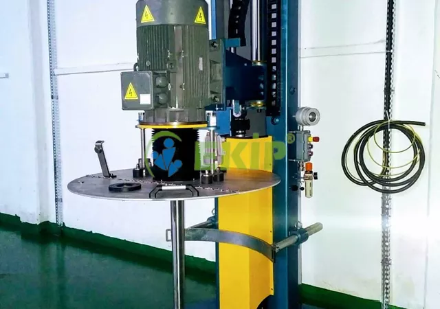
Disperser
The liquid and solid materials within mobile tanks are mixed with the help of a Disperser. This technology is needed to achieve a homogeneous mixture through its side-to-side and up-and-down mixing system. Mobile systems provide economical and advantageous results for obtaining a mixture in different scale and model tanks. Dispersers are used in industrial areas where homogeneous mixtures are necessary. With a system having a capacity of 1.5 tons, it is possible to turn a large amount of product into a positive mixture in a short time.
Material quality and production quality have come together, creating more precise solutions through this quality product known as a column stirrer. Air is used instead of electricity in this strong and economical system, offering a more economical usage advantage through preferred air pressure as energy. The multilayer usage capability of the Disperser provides great ease for the user or operator. Our products yield very advantageous results in achieving a healthy and evenly distributed mixture.
There are mixing features suitable for the condition and structure of the product. Adjustment options are available according to the operator's preference, knowledge, and skill. While it is durable, the product option that is primarily functional allows for mixing many different materials, and suitable product solutions present themselves within the existing system. Our product examples provide you with the necessary ease regarding Disperser supply.
Dispersers (Column Mixers)
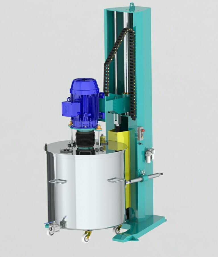
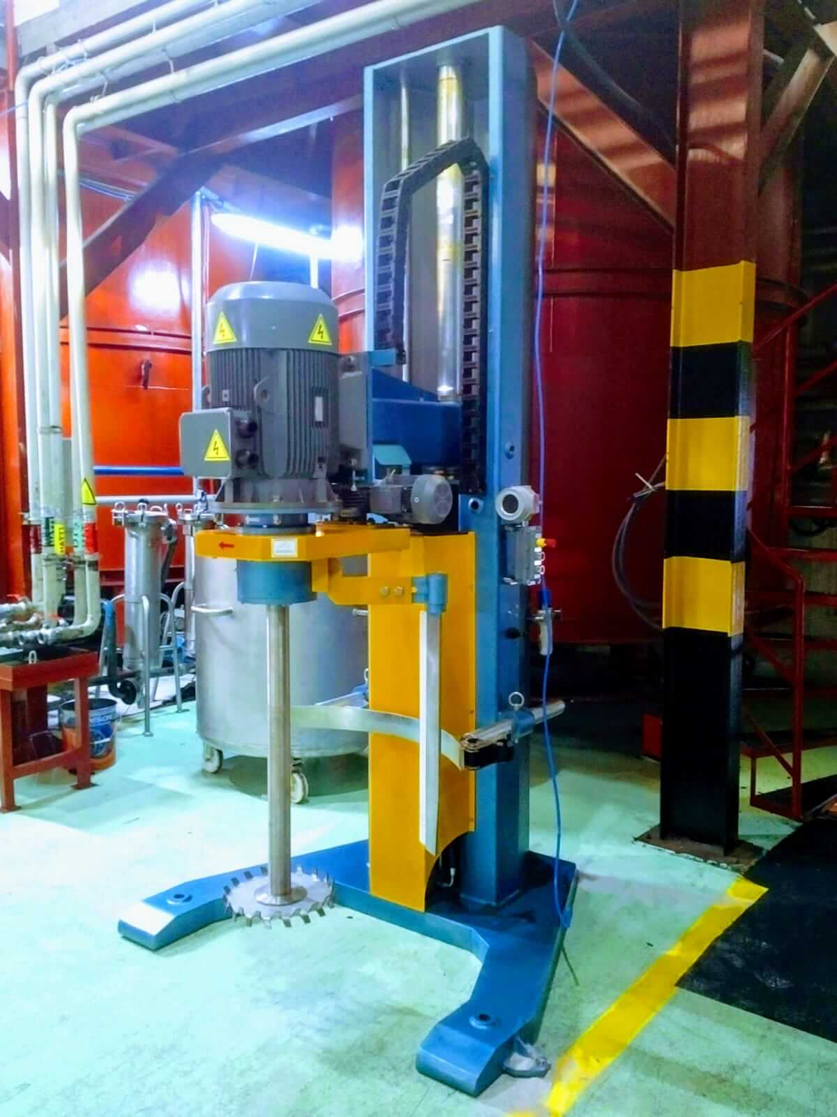
Our column mixers (dispersers), which have a utility model certificate, are generally used in the chemical industry. The aim is to mix various liquid and solid raw materials placed inside mobile tanks to obtain a product with the desired properties. It is possible to perform the mixing at the desired point and speed with a column mixer (disperser). This way, the product can be obtained in the desired consistency.
In a column mixer (disperser), the up-and-down movement of the mixer is ensured by using a hydro-pneumatic system. Since this system carries no risk of burning or explosion, it is used in systems that mix flammable and explosive products and must be ex-proof, offering much lower costs. Additionally, since this movement is performed with air instead of electricity, it provides significant energy savings. The up-and-down movement arm and rotation control buttons of the column mixer (disperser) are mounted on the mixer (disperser) column. The operator can easily monitor the mix while directing the movement. The operator can see the speed and revolution of the mix. If desired, it is possible to automatically adjust the mixing time, completion time, and mixing speed. Ekip Engineering
Design and production in compliance with international standards
High quality and long lifespan guarantee
0 – 3 m3 capacity
Special design hydro-pneumatic system
Ex-proof or IP54 motor
Special mixer design according to the product
Inverter-controlled and with speed indicator
Special type option for laboratories

1 - TECHNICAL SPECIFICATIONS:
TYPE : EKİP – 13 / 1.5
CAPACITY : 1.5 tons
MOTOR POWER : 30 KW
MOTOR SPEED : 1500 rpm
INVERTER : ABB Brand
INVERTER SETTING : 0 – 1500 rpm
2 – COLUMN MIXER INSTALLATION:
The column part of the Column Mixer will be leveled.
The bottom part will be anchored to the ground with a steel dowel.
Motor connection will be made.
The turbine type mixer connection shaft will be installed.
Motor wind guard will be installed.
Shaft run-out adjustment will be done using a comparator.
The turbine mixer will be connected to the shaft end.
Tank connection flange will be mounted, and the tank will be placed in position.
The tank will be attached to the column mixer body with a belt for safety.
Main power cable connection of the electrical panel will be done.
Column Mixer motor-panel cable connection will be done.
Control buttons and speed indicators on the Column Mixer will be connected to the panel with cables.
Air connection will be done with a size 12 pneumatic hose to the conditioner. (Air pressure will be between 6-8 bar)
The two valves on the oil tube will be opened.
3 – FIRST USE:
Use the up-and-down movement arm to lift the mixer upwards.
Place the mobile tank and secure it.
Use the up-and-down movement arm to allow the turbine mixer to enter the product and adjust the desired height for mixing.
Press the start button to operate the column mixer.
Check the accuracy of the turbine mixer's rotation direction according to the arrow direction on the turbine.
If the rotation direction is incorrect, change the phase order in the motor connection box.
Use the speed increase and decrease buttons to set the desired speed.
After use, press the stop button to stop the column mixer.
Switch the breaker on the panel to the off position.
4 – MAINTENANCE:
After using the Column Mixer, close the air connection and press the air discharge button under the conditioner to release the air.
Periodically check the oil level inside the oil tube and lubricate the shaft.
Periodically check all bolt-nut connections.
Clean the product residues on the shaft and turbine with a paintbrush after use.
Check the cooling fan and dust filters on the panel.

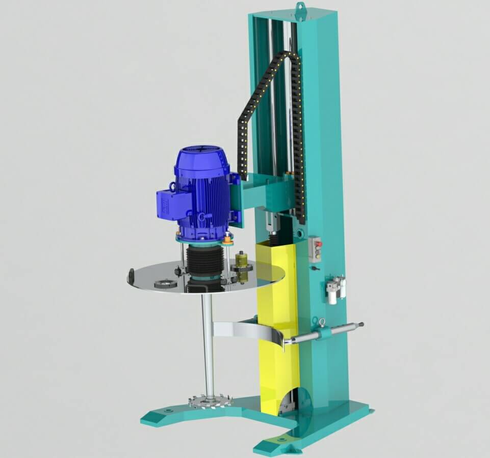
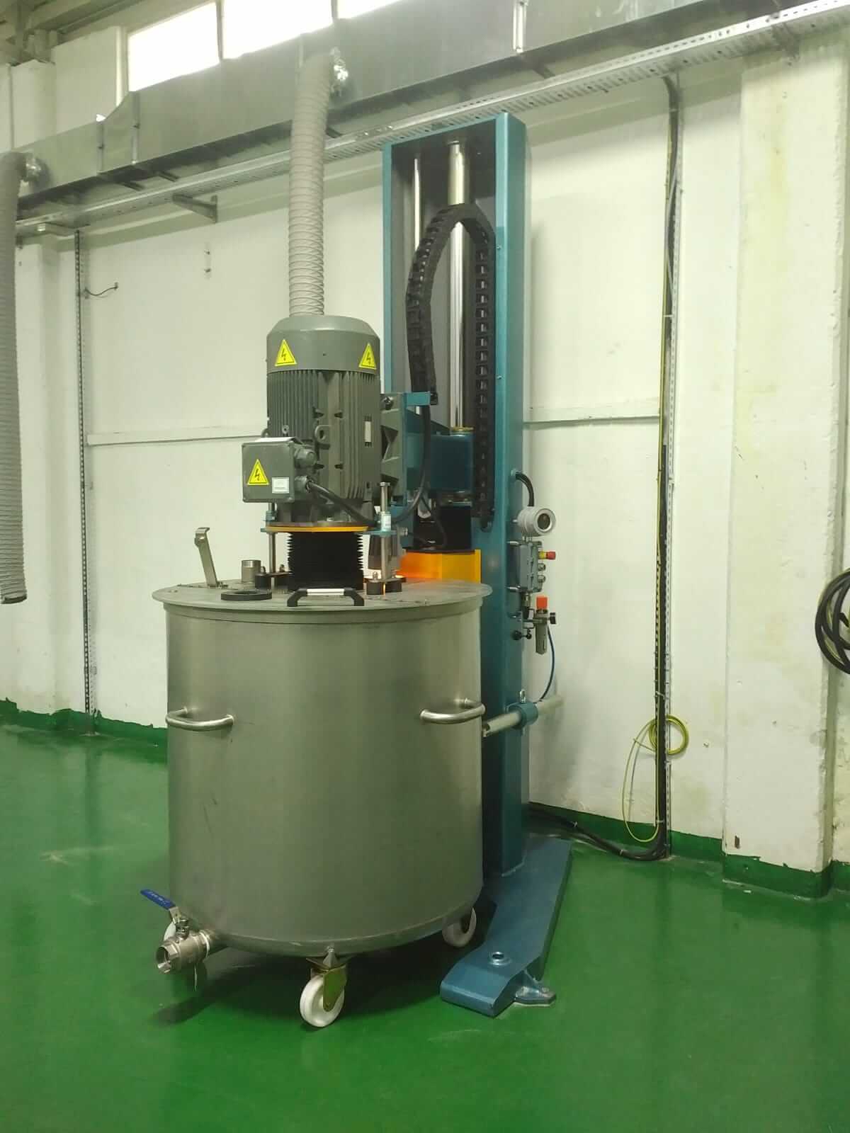
The invention is related to obtaining a product with desired properties by mixing various liquid and solid raw materials placed in mobile tanks.
The invention particularly concerns a mechanical device that enables the product to be obtained by mixing various liquid and solid raw materials placed in mobile tanks at the desired speed, at the desired point, and at low cost.
Today, in many areas of industry, mixer assemblies are extensively used for mixing various liquid and solid raw materials to obtain products with the desired properties. This intensive use in the chemical and many other sectors has made the development and renewal of mixer assemblies necessary.
Of course, different mixers are used in the known state of the art, but the mentioned mixers are characterized by the following;
The use of electric systems for enabling the up-and-down movement of the mixer stirring group, resulting in high energy costs due to these systems,
The use of systems that are required to be exproof (electrical devices that can be used in explosive environments) when mixing flammable and combustible products. Electrical devices, due to the arcs they generate as a result of static warming and operation, pose a danger to industrial facilities. The construction and use of electrical devices used in such explosive environments are different. Therefore, the necessary exproof systems (electrical devices that can be used in explosive environments) impose an additional cost on the facility.
The operator's inability to observe the mixing process while using the control levers and movement buttons of the mixer assembly, leading to an ergonomic (ease of use) issue,
The inability to automatically adjust features such as mixing times and mixing cycles, among many other disadvantages.
The objective of the invention, based on the current state of the art, is to enable the up-and-down movement of the mixer using a hydro-pneumatic system.
The purpose of the invention is to achieve significant energy savings by using a hydro-pneumatic system for the up-and-down movement of the mixer.
Another purpose of the invention, considering the necessity of using systems that must be exproof (electrically powered devices that can be used in explosive environments) when mixing flammable and combustible products, is to prevent the systems that must be exproof from imposing an additional cost on the facility, as the system carries no risk of combustion or explosion.
Another objective of the invention is to provide ease of use by mounting the up-and-down movement direction lever and rotation control buttons on the mixer column.
Another aim of the invention is to eliminate unnecessary labor and time losses by mounting the up-and-down movement direction lever and rotation control buttons on the mixer column.
Another objective of the invention is to enable the operator to easily observe the mixture while directing the movement, thanks to the ergonomic (easy to use) system created.
In a preferred configuration of the invention, it is preferred that the mixing time, mixing end time, and mixing cycle of the mixer are automatically adjusted.
The structural and characteristic features and all advantages of the invention will be more clearly understood with the detailed explanation provided by the figures given below and their references, and therefore, the evaluation should be made considering these figures and the detailed explanation.
In order to understand the advantages of the current invention along with its structure and additional elements in the best way, it should be evaluated together with the figures described below.
Figure 1: | Front and Side Views of the Column Mixer |
Figure 2: | View of the Hydro-Pneumatic System (Oil reservoir tank-special piston) |
1. Carrier foot
2. Carrier body
3. Hydro-pneumatic unit
3.1 Guiding lever
3.2 Cylinder upper inlet
3.3 Piston cylinder
3.4 Piston
3.5 Cylinder lower inlet
3.6 Oil reservoir tank outlet
3.7 Oil reservoir tank
3.8 Oil reservoir tank inlet
4. Control buttons
5. Revolution indicator
6. Main shaft
7. Balance shafts
8. Mixing group
8.1 Motor
8.2 Mixer shaft
8.3 Turbine mixer
9. Boiler stabilization unit
10. Air conditioner
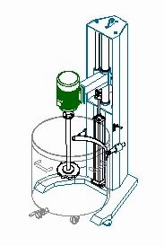
In Figure 1, the front and side views of the column mixer, which is the subject of the invention, are provided. According to this figure, the invention generally consists of a support leg (1) and a support body (2). A special piston cylinder (3) containing hydraulic oil is mounted on the aforementioned support leg (1) and the support body (2). Moreover, in Figure 2, the oil reservoir tank (3.7) which is one of the main components of the hydro-pneumatic system, detailed in the explanation, is located on the support body (2).
The mixing process is ensured by a turbine mixer (10) mounted at the end of a mixer shaft (9), which is connected to the motor (8).
The mixing speed is adjusted via control buttons (4) mounted on the aforementioned support body (2), and the mixing speed is observed through the speed indicator (5) located on the support body (2). The upward-downward movement of the aforementioned motor (8.1) occurs on the main shaft (6) and balance shafts (7) located on the support body (2).
The upward-downward movement is provided via the upward-downward movement directing lever (3.1) located on the mentioned support body (2). The air intake for the column mixer is through the air conditioner (10) located on the support body (2).
During the operation of the column mixer in Figure 2, when it is desired that the mixing group (8) (motor (8.1), mixer shaft (8.2), and turbine mixer (8.3)) move upward or downward, the operation of the hydro-pneumatic system consisting of the said oil reservoir tank (3.7) and the special piston cylinder (3.3) is shown.
During the operation of the column mixer, when it is desired for the mentioned mixing group (8) (motor (8.1), mixer shaft (8.2), and turbine mixer (8.3)) to move upward, the upward-downward movement directing lever (3.1) located on the support body (2) is lifted upwards. In this case, the air entering the oil reservoir tank (3.7) through the oil reservoir tank inlet (3.8) directs the oil in the oil reservoir tank (3.7) to move through the oil reservoir tank outlet (3.6) towards the lower inlet of the special piston cylinder (3.5), pushing the special piston (3.4) upwards and thus causing the mixing group (8) (motor (8.1), mixer shaft (8.2), and turbine mixer (8.3)) to move upwards.
Similarly, during the operation of the column mixer, when it is desired for the mentioned mixing group (8) (motor (8.1), mixer shaft (8.2), and turbine mixer (8.3)) to move downward, the upward-downward movement directing lever (5) located on the support body (2) is pushed downward. In this situation, air entering the special piston cylinder (3.3) from the upper inlet of the special piston cylinder (3.2) causes the special piston (3.4) to move downwards, and with this downward movement, it directs the oil inside the special piston cylinder (3.3) towards the oil reservoir tank (3.7) from the lower inlet of the special piston cylinder (3.5) due to the pressure applied by the air entering from the upper inlet of the special piston cylinder (3.2). In this way, the mentioned mixing group (8) (motor (8.1), mixer shaft (8.2), and turbine mixer (8.3)) is ensured to move downward.
When a mixing operation is to be carried out with the column mixer, as clearly shown in Figure 1, the portable container with the product to be mixed is fixed with the help of the vessel fixing unit (9) located on the mentioned support body (2). Using the upward-downward movement directing lever (3.1) located on the mentioned support body (2), the mixing group (8) (motor (8.1), mixer shaft (8.2), and turbine mixer (8.3)) is lowered into the container. The motor (8.1) is operated, and the mixing speed adjustment is made using the control buttons (4) mounted on the support body (2). Since the mentioned control buttons (4) and the mentioned upward-downward movement directing lever (3.1) are mounted on the support body (2), the operator can both easily observe the mixing process and control the operation.
The scope of protection for this application is defined in the claims section and is not limited to the examples described above. It is clear that a person skilled in the art can utilize similar constructions to reflect the innovation presented in the invention and/or apply this structure to other fields with similar purposes used in the relevant art. Therefore, it is evident that such structures would lack the novelty and especially the criterion of overcoming the prior art.
